|
| A Siemens Gas Turbine generator |
Using low cost natural gas, Gas Turbine power units have become more and more commonly used for normal power generation as well, replacing traditional coal or oil power plants. They have a distinct advantage that the efficiency of combustion is extremely high, so whilst they are polluting in terms of greenhouse gases, they are not responsible for soot or acid pollutants such as sulfur dioxide.
 |
| Typical gas turbine power plant |
Air Filtration in Gas Turbine Powerplants However unlike normal jet engines, operating at very high altitudes above most of the polluting dust, the air intake of a gas turbine plant is close to the ground and subject to all the pollutants that affect us all including water, soot and sand.
Therefore all GT powerplants have a pre-cleaner with a large bank of filters fitted to protect the blades from erosion and damage. Depending upon the nature of the market, the filters used differ significantly in design, material used and operational function. They divide into two classes:
 |
| Typical cylinder component of a GT element under filtration test to EN779 |
- Pulse cleanable filters: Typically these are large cylinder filters that operate to a pre-determined pressure drop then are cleaned by the simple expedient of a reverse flush of air (the pulse) to dislodge most of the dust from the filter, reducing the pressure drop to close to the clean filter. Typically these are corrugated, cellulose based filter media formed into a cylinder element. Each element assembly is often two elements attached together, a cone element and a cylinder element. These elements are designed to operate in highly dusty conditions of the Middle East where Gas Turbine power generation is the de facto process. They have to be resistant to high levels of sand dust and (for units based close to the coast), a level of water resistance from salt water in the atmosphere.
- Static filters: These are typically higher efficiency glass based media elements, with an efficiency higher than F9 to EN779, often H11 or H12 to the EN1822 test standard. These elements operate in areas of lower dust concentration in the atmosphere and where much higher levels of efficiency are demanded to protect the element housing. They are most commonly found on Gas Turbine units in Europe, with a particular requirement in offshore operations such as oilfield platforms. The need for a higher level of moisture resistance make such elements is key to their applications performance. These elements, by their very name, do not have an ability to be cleaned in service, limiting their operational lives.

Typical glass V-bank element assembly
Pressure Drop saves money and increases output...
The recent increase in filtration efficiency has been matched by an increasing demand for lower pressure drop. Vokes Air state in a White Paper that a reduction in pressure drop of 50Pa on an element for the same efficiency delivers a 0.1% improvement in power output so that a 450MW turbine can deliver an additional 450kW of power. This has to be at a given efficiency so increasing the efficiency is only one part of the equation. However, as in HVAC, the market demand will rapidly move towards a lower pressure drop technical solution.
GT element testing, until recently, was rarely standardised outside of some industry norms. For Gas Turbines operating in the Middle East, the original standard was the original 30 year old Aramco test standard. This uses a Aramco specified test dust ($10,000 per
element) up to a terminal dP of 2500 and/or 6000Pa with a typical run time of up to 84 hours and is still highly
specified by GE for gas turbine elements.
 |
| Aramco Test Stand for Gas Turbine Elements (from Northern Technical, UAE- now Donaldson) |
Flatsheet evaluation of efficiency though was undertaken using a standard Palas MFP 2000 looking at fractional efficiency.
More recently though there has been a move to the standard EN779 test protocol for HVAC. This enables the industry to require a specification to be reached. This has seen a demand for F7 to F9 filter elements. The size and number of the elements in a typical assembly means that the face velocity is actually very low in a Gas Turbine element at only 1.5cm/s versus a typical face velocity of around 11cm/s for a air intake filter for a car or 12.7cm/s for a synthetic HVAC element.
Fo glass V Bank elements, the performance requirement is measured using the EN1822 standard with a target efficiency of H11, representing a 99.8% reduction in dust reaching the turbine blade.
The additional function of pulse cleaning of elements has led to the development of a non-standard test for pulse cleanability. A typical test stand from Palas is shown below.
 |
| Palas MMTC Pulse cleaning test stand |
Known as the MMTC, this test stand feeds SAE ISO fine test dust into the sample until a pre-determined loading is reached. A reverse pulse is applied allowing the filter to be "cleaned". The clean filter is then reloaded with dust and the process repeated until a predetermined number of cycles are reached e.g. 5,000. The principle of operation is shown below. The rise in the base dP after multiple cycles is inevitable as dust remains entrained in the media following each successive cleaning pulse.
 |
| Principle of pulse cleaning |
 |
| Cleanability measurements using a MMTC Pulse clean test rig. |
The result is a slow, but steady, increase in the base pressure drop until a terminal dP is reached.
Filtration Performance of GT Elements
Pulse Clean: The typical cellulose media used for Gas Turbine applications, is similar to the performance of a Heavy Duty Air media with a permeability of around 110 to 240l/m2s at 200Pa pressure drop. At this level of permeability and pressure drop, these materials fail to achieve an efficiency better than M6 rating to EN779 at 1.5cm/s in either flatsheet or elements.
It is possible to increase the efficiency with cellulose to achieve a higher rating but at a cost of a significant increase in initial dP, which in turn limits the lifetime of the element. The best route forward to improve the performance significantly without a negative impact on pressure drop is through the use of a fine fibre layer on the upstream surface. This is applied in one of two formats:
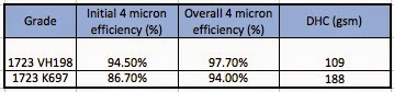
- electrospinning a ultrafine layer of polymer fibre from water of solvent onto the surface (typically less than 1 gsm) of the media. Such fibre has a diameter of around 50-150nm and significantly impacts the performance of the media. This is the basis of the Donaldson Spiderweb electrospun used in its Powercore technology and H&V's original Nanoweb treatement (though this is now a meltblown technology). The performance improvement in cleanability due to electrospun fibre is significant. as shown below. The electrospun layer has a significantly lower inherent pressure drop than the treated material in spite of the higher efficiency
 |
| Cleanability by MMTC of electrospun media compared with standard cellulose GT media |
- meltblown lamination. Melt blown polypropylene fibres are much coarser and therefore the mass required to achieve the same effectiveness in terms of efficiency. Typically the meltblown is fine fibre (average diameter close to 1 micron) and 5-10gsm is added as a lamination process with spay adhesive bonding.
The one key weakness of these solutions is the current EN779:2012 standard with IPA discharge. The soaking of the fibres with IPA both can damage the fibres (depending on polymer technology) and will significantly impact on the 0.4 micron DEHS discharge efficiency, affecting the minimum efficiency requirement and the final rating. Consequently the 2012 standard is still often not followed in the industry.
Static Filters: The fineness of the glass microfibre (to 0.3 microns) has a significant efficiency advantage over cellulose.
Summary
Gas turbine filters are critical to the performance of environmentally cleaner clean gas turbine power units and have historically been different in the functional design, pulse clean or static, based on the location of the power plant and the need for efficiency performance. Increasing demands on efficiency have been pushing the capability limits of traditional cellulose media used in pulse clean applications to the limit necessitating the use of composite technologies to add further efficiency performance.
Static filter technology is more water resistant, lower pressure drop and higher efficiency than cellulose based pulse clean technology but is more expensive and can't be pulse cleaned.
The future will demand more cleanliness efficiency in this technology plus, crucially, reduced pressure drop to maximise turbine efficiency. Whilst the bulk of installations still are glued to existing technology the capital cost of changing technology will restrain the market but newer, more modern technology paradigms will challenge the status quo, driven by the need for higher performance.
If you have any questions or queries, please let me know and feel free to contact me at any time.
Tony
Static filter technology is more water resistant, lower pressure drop and higher efficiency than cellulose based pulse clean technology but is more expensive and can't be pulse cleaned.
The future will demand more cleanliness efficiency in this technology plus, crucially, reduced pressure drop to maximise turbine efficiency. Whilst the bulk of installations still are glued to existing technology the capital cost of changing technology will restrain the market but newer, more modern technology paradigms will challenge the status quo, driven by the need for higher performance.
If you have any questions or queries, please let me know and feel free to contact me at any time.
Tony