Sunday 26 October 2014

Regulation drives innovation....Part 1 fuel filtration

I want to be very controversial today and suggest that, in spite of feelings to the contrary by those who believe that the free market should dominate the the technology trends in filtration, the function of government regulation is as important to driving innovation as any amount of customer needs. 

The reason for this statement is that in the last few years of working on filter media technology, areas where regulatory control has been strongest has driven the market to change and innovate. Where there has not been the drivers to make changes, the need for lower cost and commoditisation of products has led to a stagnation in technology. 

The two examples that I want to use are fuel media technology and HVAC. In this blog I will focus solely on fuel filtration. 

Emissions regulation driving the fuel filter market
The need for emissions control into the atmosphere is a major public health hazard globally. Couple this with the rapid growth in car and truck ownership in the Developing World we are facing a major challenge. 

Car and truck emissions of concern are:

  • soot particles from diesel trucks and cars. We discussed the filtration of soot in an earlier blog. In this case the challenge is to avoid the emission of soot in the first place. These form potentially carcinogenic particles known as PM2.5's and contribute significantly to smog in the atmosphere.   
  • NOx. The formation of nitrogen oxides is a by-product of high temperature combustion. Reducing the fuel consumption is a key route to reducing the levels of emissions. 
Both of these factors have led to increasing regulatory control globally. The leadership is driven by the Europeans through a series of emissions limits over the years known as Euro I-VI. These couple the particulate and NOx emissions and set stringent demand on new vehicles on the roads. 

Outside of emissions controls, many countries e.g. UK and Germany have used tax as a powerful lever to ensure that the cost of fuel remains high (In Germany the tax is €0,83/litre) and to drive manufacturers to be more fuel efficient and reduce the consumption of fuel. 

There are many technology requirements needed to achieve these targets including exhaust catalyst systems and with increased control on the dosing of fuel to the injection systems. The latter has driven a need for cleaner fuel in both petrol and diesel systems. 

In particular diesel powered vehicles (due to the lower fuel consumption but higher particulate emissions) has seen both a greater growth in usage and also a greater focus in terms of technology and innovation. 

Diesel fuel has a range of challenges to meet the requirements of the regulations due to its inherent dirtiness. The key issues are: 
  • water content: this varies regionally over the globe with the highest levels in China, India and Brazil. The diesel filter has to shed the water to ensure that the droplets don't corrode the the injectors and inhibit clean ignition.
  • waxes and broad chemical composition. Diesel, unlike petrol has a wider range of chemical composition with much higher molecular weight organic components. These are often waxy, particularly at lower temperatures leading to blockages of fuel filters requiring the fuel to be pre-heated to around 70C. However the sources of material for diesel also alter. Diesel is primarily a hydrocarbon from oil but, increasingly, bio-sourced components are being used for a portion of the diesel fuel e.g. rape seed oil or soya oil. The behaviour of these materials is much more aggressive to filters than traditional mineral oil based diesel.   
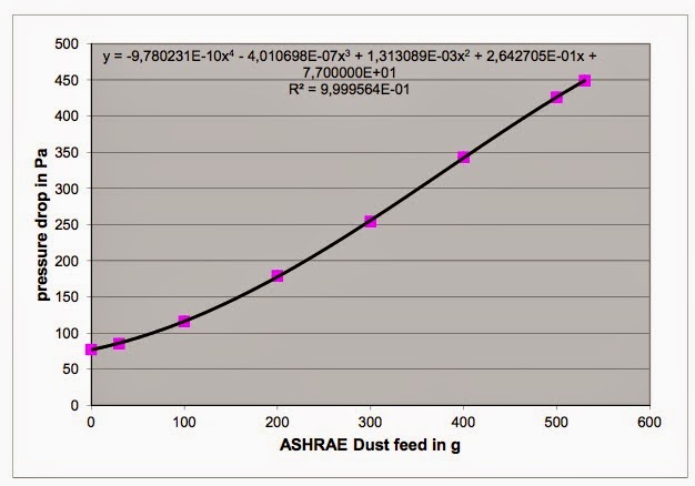
  • inherent particulate concentration in the fuel. As with water  variability n the quality standards to which diesel is manufactured leads to different levels of free particulates as can be seen from the global map from Bosch. Higher levels of particulates demand longer lifetime elements in terms of dust holding capacity. 

Increased performance specifications for diesel fuel filtration
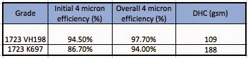
These increasing demands of performance have seen the market move significantly over the last 10 years. The demands for increased diesel fuel filtration performance has seen a move from media with 80-90% 4 micron efficiency to ISO 19438 to 99.5% 4 micron efficiency at the same level currently. This was achieved initially through the development of more efficient cellulose media, operating at the limits of a standard paper machine (1-2 cfm permeability). IN the US addition of glass increased this efficiency further. However the risks of glass fibres being washed from the filter into the fuel line, damaging the engine was not accepted in Europe. Increasing the efficiency decreases the lifetime of the element as the initial pressure drop increases. Thus composites have become required (see my previous blog on gradient density). Initially these were single layer cellulose meltblown composites with PBT (for chemical and heat resistance) but as the targets for efficiency have been driven higher by Bosch and others, the limits of cellulose have slowly been surpassed and multi layer all synthetic composites will be the requirement for the future or cellulose based composites where the cellulose acts solely as a pleatable backer to enable the material to be processable on standard pleating lines.    

The increasing need for water separation has led to the development of complex dual stage elements. Water is always present in all fuel. The water droplets in all fuel are created by the actions of pumps and are stabilised by the presence of surface active ingredients in the fuel such as lubricity additives and anti oxidants. With increasing use of bio diesel, the long chain fatty acids of natural oils also behave as surface active components, reducing the surface tension and both increasing the stability and decreasing the particle size of the droplets. The result is a need for a coalescing, water shedding pre-filter with an excellent water separation to ISO 16332. In many modern fuel filter assemblies the result is a two stage water and particle separation for diesel. 

Summary
The increasing complexity of fuel filters over the last decade has not been driven solely by process economic but by regulation. The fact that the latest standards in fuel filtration have been set in Europe are related to the increasingly tight regulations in Europe. The fact that China is still only now implementing Euro IV standards of emissions cleanliness whilst the EU is at Euro VI show that the regulatory environment is driving the technological environment. If we had left this solely to the market, would Europe have developed the most advanced fuel filtration systems in the world? Probably not- this market, like others in filtration would have ended up with low cost static performance, not the vibrancy of technological innovation. 
The high levels of environmental cleanliness are the least that our children should expect from us. For once the regulators are not wrong and are setting the standards that drive innovation. 

Wednesday 22 October 2014

Gas turbine filtration- clean air for efficient power generation

Gas turbine power plants are essentially a jet engine used to generate electrical power. Their compact size allows for their installation in remote areas such as on oil rigs or in the desert where conventional power supplies can't reach. 


A Siemens Gas Turbine generator

Using low cost natural gas, Gas Turbine power units have become more and more commonly used for normal power generation as well, replacing traditional coal or oil power plants. They have a distinct advantage that the efficiency of combustion is extremely high, so whilst they are polluting in terms of greenhouse gases, they are not responsible for soot or acid pollutants such as sulfur dioxide. 


Typical gas turbine power plant 
The principle of operation is identical to a jet engine. Huge amounts of air are taken in and mixed with the fuel and ignited. The power from the rotating turbine can be converted into steam or directly into electrical energy. 

Air Filtration in Gas Turbine Powerplants However unlike normal jet engines, operating at very high altitudes above most of the polluting dust, the air intake of a gas turbine plant is close to the ground and subject to all the pollutants that affect us all including water, soot and sand.

Therefore all GT powerplants have a pre-cleaner with a large bank of filters fitted to protect the blades from erosion and damage. Depending upon the nature of the market, the filters used differ significantly in design, material used and operational function. They divide into two classes:

Typical cylinder component of a GT element under filtration test to EN779
  • Pulse cleanable filters: Typically these are large cylinder filters that operate to a pre-determined pressure drop then are cleaned by the simple expedient of a reverse flush of air (the pulse) to dislodge most of the dust from the filter, reducing the pressure drop to close to the clean filter. Typically these are corrugated, cellulose based filter media formed into a cylinder element. Each element assembly is often two elements attached together, a cone element and a cylinder element. These elements are designed to operate in highly dusty conditions of the Middle East where Gas Turbine power generation is the de facto process. They have to be resistant to high levels of sand dust and (for units based close to the coast), a level of water resistance from salt water in the atmosphere. 

  • Static filters: These are typically higher efficiency glass based media elements, with an efficiency higher than F9 to EN779, often H11 or H12 to the EN1822 test standard. These elements operate in areas of lower dust concentration in the atmosphere and where much higher levels of efficiency are demanded to protect the element housing. They are most commonly found on Gas Turbine units in Europe, with a particular requirement in offshore operations such as oilfield platforms. The need for a higher level of moisture resistance make such elements is key to their applications performance.  These elements, by their very name, do not have an ability to be cleaned in service, limiting their operational lives. 
    Typical glass V-bank element assembly

Pressure Drop saves money and increases output...
The recent increase in filtration efficiency has been matched by an increasing demand for lower pressure drop. Vokes Air state in a White Paper that a reduction in pressure drop of 50Pa on an element for the same efficiency delivers a 0.1% improvement in power output so that a 450MW turbine can deliver an additional 450kW of power.  This has to be at a given efficiency so increasing the efficiency is only one part of the equation. However, as in HVAC, the market demand will rapidly move towards a lower pressure drop technical solution. 

Measurement of efficiency in GT filter media elements

GT element testing, until recently, was rarely standardised outside of some industry norms. For Gas Turbines operating in the Middle East, the original standard was the original 30 year old Aramco test standard. This uses a Aramco specified test dust ($10,000 per element) up to a terminal dP of 2500 and/or 6000Pa with a typical run time of up to 84 hours and is still highly specified by GE for gas turbine elements.
Aramco Test Stand for Gas Turbine Elements
(from Northern Technical, UAE- now Donaldson)

Flatsheet evaluation of efficiency though was undertaken using a standard Palas MFP 2000 looking at fractional efficiency. 

More recently though there has been a move to the standard EN779 test protocol for HVAC. This enables the industry to require a specification to be reached. This has seen a demand for F7 to F9 filter elements. The size and number of the elements in a typical assembly means that the face velocity is actually very low in a Gas Turbine element at only 1.5cm/s versus a typical face velocity of around 11cm/s for a air intake filter for a car or 12.7cm/s for a synthetic HVAC element. 

Fo glass V Bank elements, the performance requirement is measured using the EN1822 standard with a target efficiency of H11, representing a 99.8% reduction in dust reaching the turbine blade. 

The additional function of pulse cleaning of elements has led to the development of a non-standard test for pulse cleanability. A typical test stand from Palas is shown below. 


Palas MMTC Pulse cleaning test stand


Known as the MMTC, this test stand feeds SAE ISO fine test dust into the sample until a pre-determined loading is reached. A reverse pulse is applied allowing the filter to be "cleaned". The clean filter is then reloaded with dust and the process repeated until a predetermined number of cycles are reached e.g. 5,000. The principle of operation is shown below. The rise in the base dP after multiple cycles is inevitable as dust remains entrained in the media following each successive cleaning pulse.  


Principle of pulse cleaning


Cleanability measurements using a MMTC Pulse clean test rig. 
The result is a slow, but steady, increase in the base pressure drop until a terminal dP is reached. 


Filtration Performance of GT Elements
Pulse Clean: The typical cellulose media used for Gas Turbine applications, is similar to the performance of a Heavy Duty Air media with a permeability of around 110 to 240l/m2s at 200Pa pressure drop. At this level of permeability and pressure drop, these materials fail to achieve an efficiency better than M6 rating to EN779 at 1.5cm/s in either flatsheet or elements. 

It is possible to increase the efficiency with cellulose to achieve a higher rating but at a cost of a significant increase in initial dP, which in turn limits the lifetime of the element. The best route forward to improve the performance significantly without a negative impact on pressure drop is through the use of a fine fibre layer on the upstream surface. This is applied in one of two formats: 

  • electrospinning a ultrafine layer of polymer fibre from water of solvent onto the surface (typically less than 1 gsm) of the media. Such fibre has a diameter of around 50-150nm and significantly impacts the performance of the media. This is the basis of the Donaldson Spiderweb electrospun used in its Powercore technology and H&V's original Nanoweb treatement (though this is now a meltblown technology). The performance improvement in cleanability due to electrospun fibre is significant. as shown below. The electrospun layer has a significantly lower inherent pressure drop than the treated material in spite of the higher efficiency 
 
Cleanability by MMTC of electrospun media compared with standard cellulose GT media

  • meltblown lamination. Melt blown polypropylene fibres are much coarser and therefore the mass required to achieve the same effectiveness in terms of efficiency. Typically the meltblown is fine fibre (average diameter close to 1 micron) and 5-10gsm is added as a lamination process with spay adhesive bonding.  

The one key weakness of these solutions is the current EN779:2012 standard with IPA discharge. The soaking of the fibres with IPA both can damage the fibres (depending on polymer technology) and will significantly impact on the 0.4 micron DEHS discharge efficiency, affecting the minimum efficiency requirement and the final rating. Consequently the 2012 standard is still often not followed in the industry. 
Static Filters: The fineness of the glass microfibre (to 0.3 microns) has a significant efficiency advantage over cellulose. 


Summary  
Gas turbine filters are critical to the performance of environmentally cleaner clean gas turbine power units and have historically been different in the functional design, pulse clean or static, based on the location of the power plant and the need for efficiency performance. Increasing demands on efficiency have been pushing the capability limits of traditional cellulose media used in pulse clean applications to the limit necessitating the use of composite technologies to add further efficiency performance. 
Static filter technology is more water resistant, lower pressure drop and higher efficiency than cellulose based pulse clean technology but is more expensive and can't be pulse cleaned. 
The future will demand more cleanliness efficiency in this technology plus, crucially, reduced pressure drop to maximise turbine efficiency. Whilst the bulk of installations still are glued to existing technology the capital cost of changing technology will restrain the market but newer, more modern technology paradigms will challenge the status quo, driven by the need for higher performance. 

If you have any questions or queries, please let me know and feel free to contact me at any time. 

Tony

Tuesday 14 October 2014

Optimising energy consumption in HVAC Filters

Useless fact for the day....approximately 15-20% of all industrial and commercial electricity consumption in Europe is used to move air about through the powering of fans. Of this about 33% is required to overcome the resistance of the filter. This fact alone should make people appreciate the importance of filtration to our lives but also should highlight the need to be aware of the impact of energy costs with filtration. 

The filters that these facts refer to are the traditional bag or pleated filter elements that make up the many air handling units in buildings world wide. 
  

The huge amount of energy dominates the total cost of operating such a filter. A presentation made by Freudenberg at Filtrex Asia in 2011 attempted to quantify the total cost of ownership of a filter:

  • 70-80% of a filter's cost is in the power needed to maintain the element over it's lifetime
  • 20-30% lie in the purchase, installation and end of life disposal costs of a filter. 
in short the real cost of a filter is not in the material but in its operational lifetime in terms of kWh. As we have seen in other blogs this comes down to the resistance of the filter to airflow (pressure drop). If we increase the airflow resistance through higher efficiency this increases the air resistance and the power required by the fan to pull the required airflow through the filter. However as we have also seen, not all filters are created equal. A poor filter media or element design may have a negative impact on the pressure drop for a given level of efficiency. 

A second consideration is the element lifetime. All elements have recommended terminal pressure drops at which the element should be replaced. This is dictated by the environmental location of the duct so, for instance, in Shanghai we would expect to see a highly polluted atmosphere with high soot levels whilst in Saudi Arabia we would expect to see more natural dust. Both atmospheres will affect both the lifetime and selection of filter for the air handling unit (AHU) in a different way. However both scenarios have one thing in common, as the element is loaded, the amount of power required to maintain the airflow will increase and the cost of operation will increase in line with this. At some point, the cost of operation will make the replacement of the filter economically desirable. 

In the same paper Freudenberg showed this very succinctly. Reducing the pressure drop across a filter at the same efficiency extends both the lifetime and reduces the energy costs. 

Effects of dP on lifetime and energy usage of a typical bag filter (Freudenberg, Energy Efficiency in Air Filtration, Filtrex Asia, New Delhi, December 2011)
At the same conference, Sandler presented a similar paper where they showed how the replacement point in terms of pressure drop of the filter can affect the overall costs of the filter unit. 

Total cost of ownership as a function of replacement pressure drop of the element (Sandler, "Optimising Life Cycle Costs with new Synthetic Pocket Filter Media", Filtrex Asia December 2011")
The graph needs a little understanding. The costs are the total for 1500g of dust. If we assume a 100Pa initial pressure drop and replace the filter after an increase of 10Pa, then the cost of filtering the 1500g of dust becomes prohibitively high as we would be replacing the element every 30g or so. This is the solid light blue line. If we wait until the element reaches 200Pa before replacing it then the cost drops dramatically as we would expect. 

However the energy consumption is rising all the time (light blue dotted line) and the total cost of of ownership (dark blue solid line) of the filters reaches a minimum before the cost of operating the element starts to rise. 

In short there is an optimal replacement point for any element beyond which the real cost becomes uneconomic. 

This is a good academic exercise used by both companies to promote their latest and best technology. The reality of life is that most people rarely notice the filters or air conditioning let alone prioritise the service intervals for replacing a filter. This was highlighted in an excellent blog by Ken Bloom in 2004 . He highlighted the following reasons for HVAC monitoring: 
  • Reliably clean air is a resource not unlike water and power.
  • Accurate monitoring eliminates the guesswork of knowing when to replace air filters
  • Proper replacement reduces material and labor costs to monitor detect and maintain the filtration system.
  • The automated air filtration system affords greater environmental control eliminating HV AC failure and plant disruptions.
  • Air filtration monitoring reduces energy consumption when filters are changed "on time" eliminating drag on HVAC system.
  • Air filtration monitoring can assist in reducing energy consumption when higher efficiency filters are used to keep heat exchange elements clean.
Operating a filter beyond its optimal lifetime endpoint is costing money and reducing performance. A single element in a AHU could be using up to 500kWh per annum (Freudenberg, Filtrex Asia 2011) than a poor performing filter of the same efficiency. In a bank of 10 elements that is a significant amount of power consumption. 

So how can we tell optimal lifetimes? One way is by monitoring the actual performance in real life with a range of mobile phone applications that enable you to track the live pressure drop of a filter and can set alarms for replacement. 

However the best way of improving the cost effectiveness of a filter is to start off with a low pressure drop filter in the first place. As we have seen, a low initial pressure drop gives a huge advantage in terms of overall costs, more than covering the higher purchase price. 

The Eurovent ratings are a measure of the power consumption of a filter over its lifetime and from this a determination of a rating for the filter can be given in the form of a label attached to the filter cartridge. 

Typical Eurovent 4/11: 2014 energy label for a F9 filter (AAF)

Eurovent are an industry standards committee set up to set the standards for air conditioning and refrigeration systems in buildings and, as the name suggests, work on developing and implementing industry wide standards to be applied across the EU.

Eurovent ratings are calculated based on the shape of the loading curve during the EN779:2012 test at 3400m3/hour.  
EN779 loading curve with a polynomial best fit equation applied

The shape of the curve allows for a 4th power polynomial equation to be fitted:

to be fitted to the data and from this a range of constants, a, b, c, d and e are extracted. e is the initial dP of the element with no loading. 
From this a measure of the average pressure drop for the loading can be calculated from the following equation:


The constant Mx comes from the filtration rating of the element given below

Knowing the average pressure drop we can now calculate the power consumption using the following equation:
where qv is the flow rate of 0.944m3/s, t is the operational running time of 6000 hours and n = 0.5. 

Based on the power consumption we are now able to apply a rating using the following table

There are several notes. 
  • The 2014 ratings replace the ratings previously issued in 2010 covering a wider range of ratings A-G.
  • The rating has to be undertaken based on a loading undertaken at a flow rate of 0.944m3/s (3400m3/hour)
  • The DHC must be > the M minimum capacity

Summary
In summary energy consumption is a critical requirement for HVAC filtration making up 80% of the total cost of a filter installation and is often overlooked when installing an air handling system. There are several issues that the user needs to account for:
  • optimal balance between element cost and energy
  • monitoring the element pressure drop in service to ensure that the optimal replacement intervals are selected.
  • element power consumption as measured to Eurovent 4/11 2014 allowing for an 
Thank you for following me. Please feel free to contact me if you have any further questions.

Have fun...
 

Wednesday 8 October 2014

Gradient density filtration- 3 dimensional formation control!

Optimising the dust holding capacity of a media is a critical requirement these days. The typical scenario for any sales manager visiting an element manufacturer is "your media is under performing the competitor by x%" or we need a longer service interval on our elements. In a market of commoditising products, filters are an area where added value comes from added performance. 

In order to add performance we need to revisit the basics of how filter materials are manufactured and how contamination is captured. Any process for laying down non-woven fibres creates a density gradient from top to bottom meaning that the fibres are more open at the top (upstream) side of the filter material than at the bottom. The result is that the pore size at the bottom is smaller creating in effect a cone into which the contaminant falls. I've illustrated this in a very simple way below.


Simplistic view of the pore structure of a filter
This means that in an ideal world the filter will load with contaminant from the bottom upwards. As this structure is created by random fibre formation this is not a realistic picture. The reality is that the pore structure has a size distribution and is not evenly distributed. This means that for any single layer structure there is a limited theoretical dust holding capacity based on this concept. 

Gradient density structures in filtration are designed to control this process better. They all into two categories: 

  • homogenous gradient density structures formed at the same time with the same materials
  • composite layered structures of multiple materials
If we take our simple structure from above and create a gradient density illustration we see something like this. The additional volume allows for a higher level of dust holding capacity to be created.  


Simplistic gradient density filtration structure
  
The downside of this is that the media thickness has significantly increased meaning that there is less media that can be squeezed into a standard pleated element. This therefore reduces surface area and increases face velocity with the impact on DHC and efficiency previously mentioned in my blog of yesterday. The key therefore of any gradient density structures lies in adding a more open upstream side without increasing thickness significantly. This requires different fibres than on the downstream side which leads to more complex product developments. 

I will give you some examples of each of the product strategies. 

Homogeneous Gradient Density Structures- Capaceon Technology
Capaceon filter media technology from Hollingsworth and Vose is an excellent example of controlled z-directional structures. The basic material is 100% cellulose and the key to its design lies in a proprietary process that creates a two layer structure in the forming process on the paper machine with defined permeability in each stage. The result, in terms of performance is a significant improvement in media Dust Holding Capacity at any efficiency rating across the permeability range in air filters. 
Capaceon performance enhancement in air filter applications over traditional single layer materials
The advantage of this approach is two fold. It is possible to retain the same dust holding capacity and manufacture a more efficient element with the same capacity or you can take the added 35% capacity increase as a performance enhancement in element design.  

As pointed out above the media suffers from a slight increase in thickness (about 10%) compared to standard media and in order to ensure that the benefits are seen in the final element, the end user has to optimise the filter element design with slightly fewer pleats and slightly higher face velocity. 

This technology is excellent for air filtration but suffers in liquid filtration as the more open top layer is compressed in the higher viscosity and pressure drops of liquid filtration applications.

Composite Technology 
Composite technology creates a gradient density structure through multiple layers of media. The idea has been well known for many years and is used daily in media and element manufacturers through composite lamination or co-pleating different materials. 

One of the most basic example of this is the cellulose/meltblown or cellulose/synthetic (including electrospinning) technology where a standard cellulose filter media has an enhanced performance through the addition of a synthetic top layer. The top layer acts to disrupt the filter cake and adds significant capacity to the media. The advantage of meltblown (and even more with electrospun fibres) is that the fibre diameters are significantly lower than with cellulose so a high level of fibre density can be created with limited increase in thickness and, more critically, pressure drop. 

To illustrate this I have taken multipass data for a typical 180gsm modern diesel grade, 1723 VH198, manufactured by Hollingsworth and Vose and compared it to the same grade with a 50 gsm PBT meltblown, 1723 K697.


Multipass performance of cellulose filter media v cellulose meltblown composite
The data isn't perfect as the two media didn't show the same efficiency level. However the principle of performance enhancement in terms of the dust holding capacity improvement by adding the synthetic meltblown is clear. There is a >70% increase in media lifetime by the simple expedient of adding a top layer of 50gsm. The impact on thickness and pressure drop is also not significant due to the fine fibres. The resultant material now significantly moves the performance dial whilst at the same time remaining, structurally the same material and able to be pleated on standard process equipment. 

This is not just restricted to fuel media. Performance enhancements by adding very fine fibres such as electrospun, nanometre diameter fibres can significantly increase the performance of pulse clean gas turbine elements in air filtration. The recent move in this market to achieve F8 or F9 efficiency ratings can't be achieved using the traditional cellulose+ PES single layer material. The best efficiency that we saw was a significantly lower M6 efficiency rating. Through the addition of a meltblown layer (typically 10gsm of PP), this rating can be significantly improved to F8 or even F9. Some companies, such as Donaldson, use their own proprietary electrospinning technology to achieve this level of performance.    

The Composite Future  
The concept of composite filter media is moving from the specialty markets to the mainstream as end users look to increase performance advantages over their competitors or as performance specifications increase. 

Dual layer composites are no longer the norm with composite materials up to 5 or 7 layers under development for fuel applications with huge lifetimes at exceptional efficiencies (>99.6% initial efficiency at 4 microns).  

The limiting factor of the efficiency of the cellulose layer is going to be replaced by the simple expedient of an open cellulose layer, with the main efficiency layers being the synthetic layers bonded to the cellulose. This turns the cellulose from being the efficiency layer to being a pleatable backer enabling processing on standard pleating lines. 

The synthetic media itself will be extended further with finer and finer fibres being manufactured to a more consistent level at higher and higher throughput. This will require further advances in meltblown technology to achieve but the technology is slowly evolving in that direction. 

Thanks for reading this blog. If you have enjoyed it or have further topics to discuss please feel free to contact me. 

Tony 

Monday 6 October 2014

Face velocity- the unstated key factor in filter performance

One of the unstated issues in filtration performance is the unseen one of the effects of face velocity. 

Face velocity significantly impacts the measured performance of a filter in terms of lifetime and, to a lesser extent, efficiency. 

Increasing face velocity in any filter media increases pressure drop in a near linear relationship, as was discussed in the initial blog in this series. If you increase the initial pressure drop and your test (such as EN779 or ASHRAE 52.2 in particular) has a fixed terminal pressure drop then this will significantly reduce the flatsheet or even element capacity. 

Even where tests are run to a differential terminal pressure drop (i.e. initial dP + xPa) the impact of the face velocity can be significant. The simplest examples of these are in air filtration to ISO 5011. An example is shown below. A typical Heavy Duty Air filter was tested on the PALAS MFP 3000 flatsheet gravimetric test stand to a final pressure drop of initial dP + 2000Pa. The test protocol was replicated at 4.2, 11.1 and 16.7 cm/s. 

The test measured also the initial gravimetric efficiency at the initial pressure drop of Initial + 500Pa. As this grade is a typical Heavy Duty Air grade, we didn't expect to see a significant drop in gravimetric efficiency.

Effects of face velocity on DHC and gravimetric efficiency to ISO 5011
 The results show a clear drop in both efficiency and DHC. Why? 

The fundamentals of dust capture for most materials is via interception of the dust by the fibres. Secondary mechanisms exist such as diffusion but in essence for large particles such as ISO fine dust the interception rules. 

Higher face velocities add kinetic energy to the particles using the well known equation:

The higher the velocity the more the particles will penetrate the media decreasing the efficiency. The limited loss in efficiency comes down to the weight distribution of the test dust which in itself limits the ability to penetrate the media. 

The impact on the lifetime is also related to the additional kinetic energy of the particles. The dust forms a filter cake both on the surface and in the depth of the filter media. Normally this cake build up is relatively loose and particles (and airflow) can still penetrate through the filter. At higher face velocities the pressure drop increases creating a suction effect on the dust cake plus the dust cake is much more compact due to higher speed impacts reducing the ability of the media to allow airflow, through, increasing the pressure drop rapidly and leading to an early termination of the test. 

A third factor is compression due to airflow increases. As the pressure drop increases the pressure drop causes media compression and thinning increasing the pressure drop further. In depth filters such as HVAC filters this can be quite significant and causes a non lienar pressure drop response.

A similar trend is seen with liquid filtration. The multipass test for fuel ISO19438 was used to demonstrate the impact of face velocity on efficiency and DHC of a next generation composite synthetic fuel media earlier this year. 

Here the settings were for a 200 sq. cm sample with the multipass flowing at 0.5 l/min and 1.5 l/min.  The results are very similar to the air sample with a significant drop in lifetime and also a drop in both initial and overall efficiency. 


The face velocity effects are very general in all filtration media and test standards and therefore the face velocity should be stated on all tests. The problems often arise not in the flatsheet testing but in elements. 

With cost pressures on elements, there is always pressure to reduce the amount of media in an element. Decreases in the area of media in an element will always lead to a loss in performance. 

Another element issue is poor element design which leads to pleats or bags pressing together under flow, restricting the available filtration area, increasing the face velocity and pressure drop with the same effects. 

In summary, face velocity is a variable that you ignore at your peril in filtration. It leads to lower performance both in terms of efficiency and lifetime. 

Have fun....

Tony